

Iron Casting Manufacturer: Mastering Precision and Durability for Modern Industries
2026-09-23
Cast iron fails when tolerances drift or graphite forms unevenly—yet most buyers don't realize this until a critical part gives out on the line. Zhaoyuqi operates on a different assumption: that precision and durability are not trade-offs, but two sides of the same metallurgical discipline. From ductile iron's nodular graphite to controlled cooling curves, the differences are invisible to the eye and massive in service life. Here's what that discipline looks like in practice.
Melt Control Led by Spectrometer Readings, Not Guesswork
The shift away from guesswork in melt control starts with real-time spectrometer data. Instead of relying on the operator's gut feeling or past experience, the reading directly tells you when the carbon content is drifting out of spec or when the silicon needs a trim. A foundry supervisor no longer has to wait for a lab test that takes twenty minutes and interrupts the pour. The spectrometer, positioned right at the furnace, catches deviations while the metal is still molten, and the adjustment is made immediately.
This approach changes the whole rhythm of the melt shop. You stop chasing problems after they have already shown up in the casting. The spectrometer readings become the primary guide, not a confirmation after the fact. It is the difference between steering a car by watching the road ahead and steering by looking in the rearview mirror. When the numbers on the screen say the chemistry is off, you act before the pour, not after the scrap pile grows.
Green Sand, Resin Shells, or Lost Foam? Matching Mold Method to Part Geometry
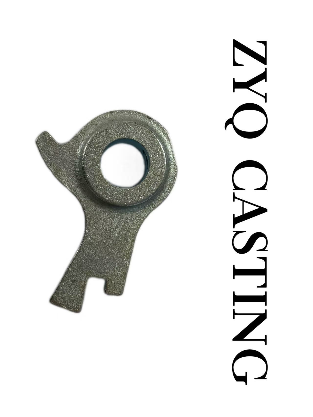
Choosing between green sand, resin shell, and lost foam isn't just a foundry preference—it's a geometry-driven decision. Green sand excels when your part has moderate complexity and doesn't demand razor-thin walls or deep pockets. The natural permeability of the sand handles gassing well, but the mold's rigidity limits how far you can push intricate coring or extreme dimensional tolerances. If your casting features deep recesses, thin ribs, or frequent section changes, green sand may force you into looser tolerances or extra machining stock.
Resin shell comes into its own when the part geometry calls for sharper edges, smoother surfaces, or thinner walls in the 3–6 mm range. The pre-coated sand sets hard under heat, producing a mold that holds its shape far better than green sand. That stiffness lets you cast tighter features without excessive draft, and the lower gas evolution means fewer surface defects on thin sections. However, the shell process loves symmetry and open cavities—complex undercuts or blind internal passages can make core removal a headache.
Lost foam shines where other methods choke: highly complex parts with internal voids, integrated passages, or shapes that would need a dozen separate cores. Because the foam pattern stays in the mold and vaporizes during pouring, there are no parting lines or core prints to fight. This lets you cast parts with undercuts, variable wall thicknesses, and nearly net-shape geometry in one shot. The trade-off is surface finish and process control—foam decomposition can leave carbon residue if the gating isn't tuned, and very thin walls risk collapse before metal fills the cavity. Match the method to the part's geometry, not the other way around.
Pouring Temperature Curves That Prevent Cold Shuts and Misruns
Cold shuts and misruns usually appear when the metal loses too much heat before two fronts can merge or before the cavity fills completely. A controlled pouring temperature curve keeps the alloy above its liquidus for the whole journey from furnace to mold, without pushing superheat so high that shrinkage or gas defects take over.
The curve itself is a falling line, not a single set point. It begins with the tap temperature, dips during transfer and pouring, and keeps dropping inside the mold. Thin sections need a hotter start or a faster pour to lift the far end of the curve, while thicker castings can work with a gentler slope. Thermocouple readings at the ladle and ingate show exactly where the heat is being lost, so adjustments can be made before defects show up.
Ladle preheat, pouring speed, and even mold coating all bend the curve in small but useful ways. The aim is to keep the leading edge of the metal fluid long enough for it to fuse with the next stream, rather than simply pouring at a higher temperature and hoping for the best.
Why Surface Prep After Shot Blasting Affects Coating Adhesion
After shot blasting, the steel surface often looks uniformly rough and clean, but that alone doesn't guarantee strong coating adhesion. Blasting leaves behind fine dust, fractured abrasive particles, and sometimes invisible salts or oils pressed into the peaks and valleys of the anchor profile. If these residues aren't removed, the coating bonds to the dust layer instead of the metal, so adhesion fails early even when the profile depth was within specification.
The condition of a blasted surface also changes quickly once it's exposed to air. Humidity can cause flash rusting within hours, and temperature swings bring condensation into the micro-crevices. A profile that was perfectly receptive right after blasting can become passive or contaminated by the time coating starts. That's why vacuuming, dry air blowing, or solvent wiping after blasting isn't a formality—it resets the surface so the coating can wet out properly.
Post-blast surface prep also removes loosely bound peaks and sharp edges left by the abrasive. Those brittle high spots can break under coating stress, creating micro-cracks that let moisture creep underneath. A quick sweep or light brushing knocks them off and leaves a more stable profile, which improves long-term adhesion rather than just initial pull-off values.
Austempering for Gears and Wear Plates That Outlast Conventional Heat Treat
Gears and wear plates live hard lives. They take rolling contact, sliding friction, impact, and repeated flexing until the surface finally gives up. Conventional quench-and-temper processing leaves a part that is hard on the outside but often brittle underneath, with distortion that has to be machined back at extra cost. Austempering changes this equation by transforming the steel into a single tough structure called ausferrite instead of conventional martensite. The result holds high hardness without the usual penalty in ductility, and the part comes out of the salt bath with far less movement, meaning less post-heat-treat grinding.
What this means in service is a gear tooth that resists pitting and bending fatigue longer than a conventionally hardened tooth at the same surface hardness. Wear plates behave the same way: they absorb gritty abrasion while absorbing impacts that would crack a through-hardened plate. Because austempering uses a controlled-temperature bath rather than a violent quench, residual stresses are lower and more uniform, so thin sections, splines, and keyways stay closer to print. The process works best on medium- to high-carbon steels and ductile iron, making it a practical upgrade for parts that currently fail by chipping, spalling, or premature fatigue.
For manufacturers tired of replacing gears and wear plates on a set schedule, the advantage is simple: austempered parts stay in the machine longer. They can be specified to a lower case hardness than a carburized part and still deliver equal or better life, or they can be run harder without turning brittle. The bath temperature and time control the final properties, so the same furnace can produce a tough core for one job and a harder, more wear-resistant surface for the next. That flexibility, combined with reduced straightening and grinding, often makes austempering cheaper per hour of actual service than conventional heat treating.
Coordinate Measuring Machines and 3D Scanning for Every Critical Dimension
Dimensional inspection often splits into two camps: tactile probing on a CMM for geometric tolerances, and optical 3D scanning for dense surface data. The real advantage comes when both are run against the same CAD nominal, so a bore position checked by touch can be cross-verified against a scanned point cloud without switching reference frames.
On parts with tight form controls or deep internal features, a CMM still earns its place because it returns repeatable, traceable measurements even on reflective or machined surfaces that confuse structured light. 3D scanning fills the opposite gap where hundreds of thousands of points are needed to understand warpage, profile variation, or complex freeform contours. Using a shared alignment strategy keeps both datasets usable in one report.
The practical workflow is usually not either/or. A scanner can quickly map a first article and flag areas that drift out of tolerance, then a CMM verifies those specific callouts with the required uncertainty. This avoids programming lengthy probe paths for every feature while still keeping critical dimensions on a defensible metrology backbone.
FAQ
It usually comes down to pattern design, gating placement, and a foundry that treats simulation as a daily habit rather than an occasional check. We adjust shrinkage allowances for each section's thickness, use chills where solidification order matters, and pour at a controlled temperature band. That prevents the usual battles between machining allowances and distortion, so the casting arrives ready for finishing instead of needing rescue work.
Heavy construction, mining, rail, and fluid power come to mind. Mining equipment sees constant impact and abrasive wear; rail components face cyclic loading and extreme temperature swings; hydraulic manifolds need pressure integrity without hidden porosity. Each requires a different alloy tweak and a different testing focus—impact toughness for one, leak-tightness for another.
You treat each heat as its own small experiment. Fast chemical analysis before pouring, inoculation counts that match section sensitivity, and a record that follows the ladle rather than just the part number. We also section a sacrificial casting from each shift when the customer's application is critical—microstructure tells you more than a surface hardness reading ever will.
Sharp internal corners and abrupt section changes. They create stress risers and feeding problems at the same time. A small radius or a tapered transition can make the difference between a part that survives shock loading and one that cracks during proof testing. We usually ask for a three-day design review early, because moving a rib by a few millimeters later costs far less than adding a radius after tooling is cut.
It is not a one-to-one substitute, but it often outperforms steel where stiffness, vibration damping, and castability matter more than weldability. In components like axle housings, gear carriers, and pump bodies, ductile iron gives you strength in the 60-40-18 or 80-55-06 range while cutting machining time compared to a fabricated steel assembly. The key is matching the grade to the actual load case, not just swapping materials on a drawing.
Ask how they handle process changes. A foundry that can show you a dated change log for sand system adjustments, pouring temperature shifts, or pattern repairs is one that understands traceability. Also check whether they keep first-article samples from each pattern for reference. That kind of discipline predicts fewer field surprises than a wall full of certificates.
Simulation lets you test gating and riser layouts on screen before cutting steel. That means we can spot shrinkage or cold shut risks in a day instead of discovering them after a sample run. It also allows us to reduce the number of prototypes from three or four to often one, which saves weeks. The catch is that simulation only works if the material database and boundary conditions match your actual shop floor—so we validate with a short pilot pour on complex jobs.
It usually traces back to cooling rate and inoculation. If the iron solidifies too fast in thin sections, you get hard carbides that wear inserts quickly. If cooling is uneven, you get hard spots mixed with soft ferrite. Consistent shakeout timing, controlled sand moisture, and proper ladle inoculation keep the graphite structure uniform, which is what makes machining predictable. We also check hardness on the actual machined surface, not just a separately cast test bar.
Conclusion
A capable iron casting manufacturer treats the melt as a measurable science rather than a tradition. Spectrometer readings dictate every adjustment to chemistry, ensuring the iron arrives at the mold with the exact carbon equivalent, silicon balance, and trace elements needed for the part's service conditions. That same attention to process carries into mold selection: green sand offers cost-effective flexibility for moderate volumes, resin shell molds produce crisper surfaces for complex profiles, and lost foam shines when internal passages or near-net shapes make pattern removal impractical. Pouring temperature curves are plotted against section thickness and alloy composition, preventing the cold shuts and misruns that plague under-heated metal while avoiding the shrinkage and gas defects of overheating.
Precision does not stop at the shakeout. Shot blasting cleans the casting but also conditions the surface—a step often overlooked until coatings peel or corrosion creeps beneath the finish. Proper blast media, angle, and duration leave a profile that anchors primers and paints. For components facing cyclic stress or abrasive wear, austempering transforms conventional ductile iron into a structure of ausferrite, giving gears and wear plates a fatigue life and hardness that outlast ordinary quench-and-temper treatments. Finally, coordinate measuring machines and 3D scanning audit every critical dimension, comparing the as-cast geometry to CAD models in minutes. The result is an iron casting that holds tolerance, resists wear, and performs predictably in modern industrial systems.
Contact Us
Contact Person: Nico Yin
Email: [email protected]
Tel/WhatsApp: 8618561567088
Website: https://www.ductileironparts.com/