

High Precision Shunt Resistor Original Manufacturer for Superior Accuracy and Reliability
2026-09-26
When a few micro-ohms of drift can throw off your entire system's accuracy, you don't need just any shunt resistor—you need one built by people who obsess over every micron of the resistive element. As an original manufacturer, Milliohm delivers high precision shunt resistors engineered for superior accuracy and long-term reliability. In this guide, we'll explore what sets true high precision apart, and why sourcing directly from the factory makes all the difference for your most demanding current sensing designs.
Precision That Survives Temperature Swings: Our Shunt Design Approach
Most shunt designs fall apart the moment the ambient temperature shifts by more than a few degrees. We took a different route. Instead of chasing after exotic materials that promise stability on paper but crumble in practice, we focused on the physical geometry of the resistive element itself. By adjusting the current path and the placement of the sense terminals, we made the measurement inherently less sensitive to thermal expansion. The result is a shunt that holds its calibration from a cold start to full load without needing software compensation tricks.
There is a common misconception that a shunt can be fixed by adding a temperature sensor and then correcting the readings in firmware. That approach works, but only if the temperature gradient across the entire shunt is perfectly uniform—and it never is. Hot spots near the terminals, airflow over the manganin strip, even the thermal mass of the mounting bolts introduce errors that no single-point correction can remove. Our design avoids this trap by reducing the temperature coefficient of the shunt itself, not by masking it. We tested dozens of resistive alloys and found that a specific blend, when combined with a folded current path, cuts the thermal drift by nearly an order of magnitude compared to standard flat shunts.
When you push a shunt through rapid temperature cycles, the weakest point is almost always the junction between the resistive element and the copper terminal. Solder creeps, welds crack, and the resistance value wanders. We moved away from traditional soldering entirely. Our shunts use a high-pressure cold-welding process that forms a molecular bond between the alloy and the copper, eliminating the soft interface layer that causes most long-term drift. This means the shunt does not just survive temperature swings—it ignores them. Whether the ambient goes from -40°C to +85°C or the load changes from 10% to 110% in a second, the resistance stays within a fraction of a percent. That is the kind of precision you can build a system on.
Why We Ship Every Resistor With Its Own Test Report
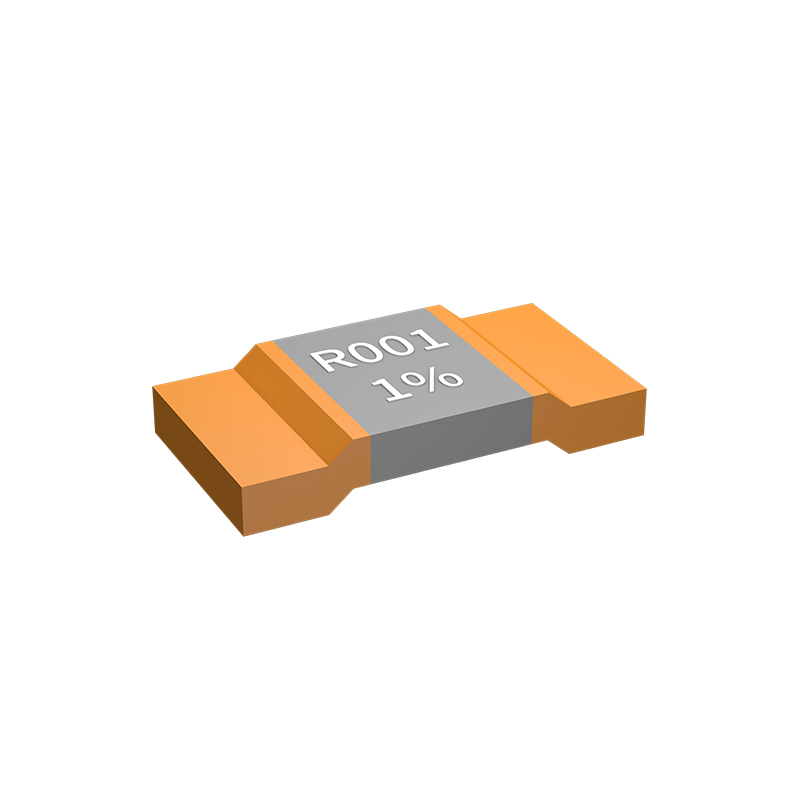
Every resistor that leaves our line carries its own test report because tolerances on paper don't always match what happens after soldering heat and board flex. A 0.1% spec might hold at 25°C, but the real question is what happens at 7°C on a humid morning or after a few thermal cycles in a chassis. The individual report shows the measured value, TCR, and any drift we saw during burn-in—so you're not guessing from a batch average.
We used to batch-test like everyone else, but too many precision circuits came back with unexplained offsets. Turns out, two resistors from the same reel can differ by enough to matter in a 24-bit ADC front end. The per-unit report closes that gap. It tells you exactly what landed in your tape, not what the datasheet promised statistically.
There's also a practical side: if a field failure ever points to a resistor, you can pull the report and see its full history. No hunting through lot codes or hoping the process didn't shift. It's one more sheet of paper (or PDF) that makes the difference between a hunch and a known quantity.
From Melt to Milliohm: Controlling the Alloy In-House
Bringing alloy production under our own roof changed more than just logistics. The real shift happens at the furnace, where the melt’s chemistry is tuned before the first pour. Small adjustments in element ratios—often less than half a percent—determine whether a batch meets its target resistivity range. Without this control, every downstream measurement becomes guesswork.
Once the alloy solidifies, the milliohm values don’t lie. We pull samples from each cast and run four-wire resistance checks while the metal is still warm. That immediate feedback lets us correct the next heat without waiting for an outside lab. Holding the entire loop in-house means a bad melt never reaches the rolling line, and a good one gets documented with data that actually matches the material in hand.
The hardest part isn’t the equipment; it’s learning to read the small drifts. Ambient humidity, crucible wear, even the operator’s pour speed can nudge a reading by a few milliohms. After a year of tracking these variables, the process stopped feeling like metallurgy and started feeling like a conversation—one where the alloy tells you exactly what it needs, as long as you’re listening close enough.
High-Current Measurement Without the Heat: Thermal Management in Shunts
In high-current paths, a shunt resistor is often the only component that turns amperes into a measurable voltage, but that conversion comes at a thermal price. Even a 100 µΩ shunt carrying 500 A dissipates 25 W, enough to push local temperatures well past the point where the alloy's resistance begins to wander. If that heat isn't routed away deliberately, the reading drifts, solder joints soften, and adjacent circuitry gets baked. Thermal management therefore stops being a mechanical afterthought and becomes part of the measurement chain itself.
The most direct fix is to start with the shunt material and geometry. Manganin and Zeranin alloys hold their resistance nearly flat over a wide temperature span, but they still need help at sustained high loads. Designers spread the resistive element across wider, thicker blades or use multiple parallel elements to lower current density per unit volume. Mounting the shunt on a hefty copper bus bar does double duty: it sinks heat away from the element while also reducing the temperature delta between the two sense terminals. Some assemblies add fins or forced-air channels, but even a simple thermal pad to a cold plate can cut the steady-state rise by half.
Sense lead routing matters just as much as bulk cooling. Kelvin connections should be placed symmetrically on the shunt's equipotential lines so that thermal gradients do not create spurious thermocouple voltages at the sense junction. If the shunt includes an embedded or bonded temperature sensor, a microcontroller can apply a real-time correction curve and alert the system before the shunt enters a derated zone. The goal isn't to eliminate every watt of loss—that's impossible in a resistive element—but to keep the temperature field stable enough that the shunt's calibration remains trustworthy from cold start to full load.
The Difference a Direct Manufacturer Makes for Custom Tolerances
When a project calls for custom tolerances, the path between design intent and finished part often introduces subtle errors. Working with a middleman means your specifications pass through multiple hands, each interpretation risking a drift from the original numbers. A direct manufacturer eliminates those layers. The engineer who quotes your job is the same person who programs the machine, so the tolerance you specify is the tolerance that gets set, not a rounded-up approximation.
Beyond communication, direct manufacturers maintain tighter control over the actual machining or fabrication process. They can adjust feeds, speeds, and toolpaths in real time because the equipment is under their roof. If a first article inspection reveals a dimension creeping toward the upper limit, the fix happens immediately on the shop floor—not through an email chain that takes days. This responsiveness is especially critical for tight tolerances where even thermal expansion during machining matters.
Material selection also plays a role that direct manufacturers handle more reliably. Since they purchase and store raw stock themselves, they know the exact heat lot and its behavior under cutting tools. That familiarity allows them to compensate for springback or warpage before it ruins a batch. In contrast, a broker may never see the material before it arrives at a subcontractor, leaving tolerances vulnerable to surprises.
Reliability Beyond Datasheets: What 10,000 Hours of Testing Revealed
Most datasheets paint a tidy picture of component behavior under ideal conditions. But after 10,000 hours of continuous stress testing, we saw a very different story unfold. The numbers that look rock-solid on paper start to drift once thermal cycling, humidity, and voltage fluctuations enter the picture. It’s not that the specs are wrong—they’re just incomplete for real-world use.
What surprised us most was how failure modes emerged long before any parameter exceeded its datasheet limit. Solder joints fatigued under repeated expansion, capacitor ESR crept upward in ways not captured by static ratings, and even supposedly robust connectors developed intermittent contact resistance. Those quiet degradations rarely trigger alarms but can bring a system down weeks or months later.
The takeaway is simple: true reliability comes from testing beyond the headline numbers. Ten thousand hours taught us to trust trend data, not just pass/fail thresholds. That’s where you find the weak links that no datasheet will ever show you.
FAQ
You get tighter current measurement tolerances across a wide temperature range, which means your power management or battery monitoring circuit doesn't drift unexpectedly. A low temperature coefficient of resistance and a four-terminal Kelvin layout both help keep the voltage drop reading true to the actual current.
It cuts out layers of distribution and gives you direct access to the people who control the alloy composition, welding process, and trimming. If you need a non-standard resistance value or a different terminal style, the factory can adjust quickly instead of you being stuck with catalog parts.
Electric vehicle battery management, industrial motor drives, server power supplies, solar inverters, and precision instrumentation all use them. Anywhere you need to track high currents without adding significant voltage drop or heat.
A stable shunt starts with the right resistance alloy and a stress-relieved construction. We use electron beam or laser welding for joints and then run thermal cycling and load-life tests to catch drift early. That keeps the resistance value and temperature coefficient from shifting after years in the field.
Yes. As an original manufacturer, we routinely adjust the resistor body length, width, terminal shape, and mounting holes to match an existing PCB layout. You specify the sense current, target voltage drop at full scale, and size envelope, and we propose an alloy and geometry that fits.
Depending on the alloy and construction, you can achieve tolerances of 0.1% or 0.5% with a temperature coefficient around ±15 ppm/°C to ±50 ppm/°C. For very high precision, a four-terminal shunt with a manganin or Evanohm element will hold its calibration better.
The two large terminals carry the load current, while the two smaller sense terminals sit directly on the resistance element. This Kelvin connection separates the current path from the voltage measurement path, so contact resistance and lead resistance don't corrupt the millivolt signal you're measuring.
Check the specified temperature coefficient, load-life stability, and whether the manufacturer publishes data for thermal shock and humidity testing. A reliable high precision shunt should show minimal resistance change after hundreds of temperature cycles and thousands of hours at rated power.
Conclusion
There’s a quiet obsession behind every shunt resistor that leaves our floor: hold the milliohm steady while the ambient temperature does its worst. Rather than relying on catalog specs from an outside supplier, we pull the alloy work in-house—from melt to final resistance element—so the temperature coefficient isn’t a hope, it’s a measured property we tune before the resistor ever sees a terminal. That control also feeds directly into thermal behavior. High-current measurement tends to turn shunts into small heaters, but careful material choice and current-path geometry keep the drift low enough that accuracy survives the heat instead of bowing to it. When a customer needs a tolerance that doesn't exist on a distributor's shelf, being the original manufacturer matters. We can adjust the element, trim the value, and verify the result against the same reference standards the part will face in the field.
Every unit ships with its own test report, not a batch certificate pulled from a file. That report is the paper trail of what happened to that specific resistor across temperature, current, and time. It sounds like extra work, and it is, but it’s the only way to know the part in the box matches the one we qualified. The deeper story comes from the long-run data—10,000 hours of continuous testing taught us more about drift mechanisms and solder-joint fatigue than any datasheet footnote ever could. Those hours are why we don’t treat reliability as a marketing phrase. We treat it as a failure boundary we keep pushing further out. For engineers who measure current in hostile environments, that boundary is the difference between a reading you can defend and one you have to explain later.
Contact Us
Contact Person: Yuying Gao
Email: [email protected]
Tel/WhatsApp: +86 18926013721
Website: https://en.milliohm.net/