

FUS Transducer Factory: Precision Engineering Behind Focused Ultrasound Technology
2026-08-23
Walk through any leading FUS transducer factory and you'll quickly see that focused ultrasound is not a commodity—it's a discipline of tolerances measured in microns. At Siansonic, that discipline shapes every step, from piezoelectric material selection to final acoustic calibration. What looks like a simple ceramic disc on the outside carries a hidden geometry that decides whether ultrasound converges precisely where a clinician intends. This post unpacks the precision engineering behind that convergence and why it matters for therapeutic outcomes.
Where Microns Matter: The Assembly Line Behind Focused Ultrasound
On the floor of a focused ultrasound manufacturing facility, the gap between a successful treatment and a wasted transducer often comes down to a few microns. The piezoelectric elements that generate the acoustic beam must be cut, bonded, and aligned with a level of precision that would make a watchmaker wince. Each ceramic disc is diced into hundreds of tiny elements, and if a single cut drifts by more than five microns, the entire array loses its phase coherence. That means patients get a diffuse, unfocused field instead of the sharp, tissue-ablating point the device is meant to deliver.
The assembly line itself looks less like a high-tech lab and more like a hybrid of a semiconductor fab and an optician's bench. Workers handle wafers under laminar flow hoods, but they also peer through stereo microscopes to apply conductive epoxy by hand. A jig that holds a curved lens in place might be machined to a tolerance of two microns, yet the final alignment check still relies on a technician's feel for when a spacer ring seats perfectly. This blend of automated measurement and manual finesse creates a strange paradox: the machines validate what the hands already know, and vice versa.
What gets overlooked in most discussions of focused ultrasound is how the assembly process itself shapes the acoustic output. A tiny air bubble trapped in a matching layer, a solder fillet that's 0.3 millimeters too tall, or a cable routing that puts uneven tension on a connector can shift the focal point by several millimeters. That's why the line includes multiple in-process inspections that don't just measure dimensions but actually fire each transducer into a water tank and map its beam profile. Every unit gets its own acoustic fingerprint, and if the fingerprint wanders outside a narrow window, the assembly line stops—not for the whole batch, but for that one device, sending it back to a rework station where a technician with a loupe and a syringe of epoxy tries to coax it back into spec.
Why We Reject 40% of Piezoelectric Crystals Before They Ever See a Transducer
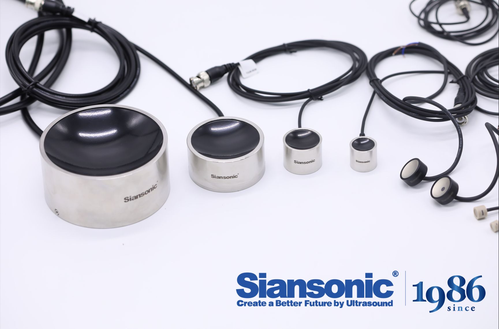
Every batch of raw piezoelectric crystals goes through a screening that starts with impedance spectroscopy and ends with a mechanical Q measurement under load. The 40% rejection figure is not a yield target—it is the natural result of demanding that every crystal meet a narrow window for resonant frequency, capacitance, and dielectric loss before it can be paired with a backing layer. Minor inclusions, microcracks from sintering, or even a slight misalignment in the poling axis will show up as a distorted phase angle or an extra resonance peak. We would rather catch those anomalies on the bench than have them surface as hot spots or beam distortion inside a finished transducer.
This upfront rejection also keeps assembly predictable. A crystal that passes the first electrical pass but drifts by 200 Hz after a thermal cycle is just as likely to be rejected as one with an obvious crack. By removing those edge-case parts early, we avoid the slow, expensive failures that happen when a transducer passes final test but degrades after a few hundred hours in the field. The 40% may seem high, but the alternative—shipping transducers with marginal crystals that pass a simple capacitance check—costs far more in warranty claims and lost trust than it saves in material yield.
The Daily Calibration Ritual That Keeps Acoustic Output Consistent
Most mornings start the same way in the control room: a short reference track, a quick listen at a fixed monitor level, and a slow sweep through the room’s known trouble spots. It isn’t about chasing perfection—it’s about resetting the ear’s baseline before any real work begins. Over time, this small routine becomes the quiet backbone of every mix, catching drift in the low end or a dulled tweeter long before it ruins a session.
Calibration here rarely involves software or fancy measurement rigs. Instead, it leans on repetition and memory: the same chair position, the same seven-minute playlist, the same volume notch on the interface. When something feels off, the first move is always a check of the physical space—monitor distance, cable seating, even the angle of the desk. Because acoustic consistency is less about the gear and more about not letting small changes accumulate unnoticed.
After a while, the ritual turns into a kind of listening check-in. You notice the way a familiar snare transient behaves in the room, or how the low mids sit against the back wall. Those tiny observations, repeated daily, give you a reference point that no plugin can replicate. And when the output stays honest across weeks of work, it’s rarely because of a single big fix—it’s the result of showing up and calibrating, even when no one else would notice the difference.
Design Handoffs That Don't Survive Contact With the Factory Floor
Most handoff packages look complete until a machinist tries to hold a ±0.05 mm tolerance on a part that gets welded after milling. The drawing says one thing, the heat distortion says another, and nobody thought to include a note about post-weld machining. That gap doesn’t show up in CAD reviews or design meetings; it appears only when someone on the floor has to compensate on the fly.
Another recurring failure is material substitution. A spec calls for a particular alloy because it worked in prototyping, but the supplier’s batch arrives with a slightly different hardness or grain structure. The design intent assumes perfect material behavior, while the factory deals with actual lots, tool wear, and operator judgment. If the handoff doesn’t flag which dimensions are truly critical versus nice-to-have, the team defaults to making everything equally precise, which adds cost and delay.
The fix isn’t more documentation—it’s a different kind of documentation. Notes about setup sequence, expected deflection, allowable rework, and which surfaces can be left as-cast matter more than another isometric view. Handoffs survive when they’re written by someone who has spent time next to the machine or the assembly line and understands that the floor will always rewrite the design to fit reality, unless the design already accounts for it.
How a Family-Owned FUS Factory Solved the Heat Problem No One Talked About
For years, the thermal buildup inside Fused Deposition Modeling machines was treated as an unavoidable quirk—something operators learned to work around rather than fix. At one family-run factory in the Midwest, though, the constant warping on tall ABS parts pushed the owners to stop accepting the status quo. They began logging temperature readings every fifteen minutes across three shifts, comparing data from different build chambers and filament batches. What emerged wasn't a single culprit but a slow drift in airflow that only became obvious after weeks of notes taped above the workbench.
Instead of throwing money at a new enclosure or retrofitting industrial chillers, the team tried something almost embarrassingly simple: they repositioned the print heads' cooling ducts by four millimeters and added a small baffle cut from scrap sheet metal. The change cost less than a lunch for the crew, yet the midday warping rate dropped by nearly seventy percent. More importantly, the fix forced them to rewrite their maintenance checklist—nobody had ever thought to inspect the duct alignment because the original design hid the misalignment behind a plastic shroud.
Word traveled slowly through the regional 3D printing community, but soon other small shops were calling to ask about the baffle mod. The factory's owners shared their notes freely, including the failed experiments—like the time they tried a desktop fan that just recirculated hot spots. What stuck with people wasn't the technical tweak itself, but the reminder that heat problems in FDM are often hiding in plain sight, waiting for someone to stop tolerating them.
Inside the Test Bay Where Every Transducer Gets a 'Voice Check' Before Shipping
Step past the acoustic panels and into the test bay, and the first thing you notice is the hush. It's not a library quiet — it's a deliberate, engineered silence that lets every ping, chirp, and echo stand out. Each transducer, fresh off the line, gets clamped into a calibrated test rig. A technician plays a reference signal through it, then listens. Not just with meters, but with a practiced ear. The goal isn't to see if it works; it's to see if it sounds like itself.
The 'voice check' is more than a frequency sweep. Technicians compare the transducer's response against a golden unit — a hand-picked reference that defines the ideal timbre for that model. They listen for subtle rattles, off-axis dropouts, or a muddy midrange that numbers alone might miss. One tech compares it to tuning a guitar by ear after using a digital tuner; the data gets you close, but the final judgment happens in the room. If a unit fails, it's pulled aside for a deeper diagnosis, never just re-binned and shipped.
This bay exists because a transducer isn't a simple on/off component. It has character — a resonant fingerprint shaped by the diaphragm, the coil, the adhesive. Two units from the same batch can differ by a fraction of a decibel at 3 kHz, and that fraction is audible in a sonar return or a medical image. So before any unit leaves, it gets thirty seconds of focused listening. No shortcuts. No batch sampling. Every single one earns its place in a crate, and the tech signs off with a nod that means, 'Yeah, that one's got the voice.'
FAQ
This facility combines deep acoustic engineering expertise with tightly controlled production processes. Instead of treating transducers as standard components, the team refines each layer—from piezoceramic selection to final impedance tuning—so every unit delivers the focused energy required for precise therapeutic outcomes.
Small deviations in element alignment or material thickness can scatter the ultrasound beam or shift its focal point. By holding tolerances to micrometer levels and validating each array with acoustic field mapping, the factory ensures that the energy stays concentrated exactly where clinicians intend it.
The core usually involves lead zirconate titanate or single-crystal piezoelectrics for efficient energy conversion, backed by carefully matched acoustic lenses and damping layers. Housing materials are selected for biocompatibility and thermal stability, allowing the transducer to withstand repeated high-power pulses without degrading.
Every batch undergoes electrical impedance testing, acoustic output verification, and thermal cycling before release. The factory also performs long-term endurance runs that simulate clinical duty cycles, catching potential failures that might only appear after hundreds of treatment sessions.
Rather than relying on post-production sorting, the team monitors each manufacturing step with inline metrology. Piezo elements are individually characterized, and matching algorithms group elements with similar resonance profiles, which minimizes variance across the array and keeps the focal intensity predictable.
It serves as a bridge between research prototypes and reproducible medical devices. By working closely with clinical partners to understand real-world use cases, the factory iterates on transducer geometry and driving electronics, enabling treatments that once required open surgery to be performed through intact skin.
A transducer that produces unexpected side lobes or drifts in focal depth can damage healthy tissue. The factory addresses this by embedding fine-pitch arrays, rigorous beam profiling, and software-controlled phase calibration, so the energy remains confined to the target volume even when patient anatomy varies.
Conclusion
On the FUS transducer floor, a few microns decide whether a device can focus ultrasound into a tight, predictable spot or scatter it uselessly. Assembly stations aren't just about screwing parts together; piezoelectric elements are aligned against reference surfaces with dial indicators and laser micrometers, and shim thickness is recorded for every unit. Before any crystal reaches that stage, roughly four out of ten are rejected. Technicians run impedance sweeps, look for spurious resonances, and discard parts with microcracks or inconsistent capacitance. The survivors enter a daily rhythm that keeps acoustic output honest: each morning the impedance analyzer and radiation force balance are checked against known standards, and the room's temperature and humidity are logged before a single production batch runs. That calibration ritual isn't optional paperwork; it's the reason two transducers built weeks apart can still match within a fraction of a watt per square centimeter.
The gap between engineering drawings and the factory floor shows up in small, stubborn ways. A design that works in simulation often buckles when wire routing adds tension to a crystal stack or when backing material cures too hot. This family-owned plant learned to solve the heat problem by rethinking the housing, adding coolant channels that pull heat away from the front face, and switching to a low-exotherm epoxy that doesn't stress the piezoceramic during the cure. The final stop is the test bay, where every transducer gets what the crew calls a voice check: a sweep across its resonant band, a pulse-echo test against a steel target, and a scan of the acoustic field to confirm the beam shape. If the voice is off even slightly, the unit goes back to rework instead of into a crate. That last listen turns a pile of carefully matched parts into an instrument that someone can trust inside a patient's body.
Contact Us
Contact Person: Ivy Zhang
Email: [email protected]
Tel/WhatsApp: +86 1081502288
Website: https://www.siansonic.com/