

Cement Grinding Aid Manufacturer Shares Proven Ways to Boost Mill Output
2026-09-01
A 5% gain in mill output might sound modest—until you realize it can add millions to your bottom line. The catch? Most plants leave that gain on the table by overlooking one simple lever: the right grinding aid, applied the right way. At HAISEN, we've helped cement producers around the world turn that lever into a competitive advantage. This post walks through the exact methods our engineers use to boost mill output, cut energy use, and keep your finish quality intact.
Why Your Mill’s First Chamber Is Leaving Tonnage on the Table
Most operators keep an eye on the total mill output, but they rarely trace the bottleneck back to the first chamber. That chamber does the heavy lifting: it takes the incoming clinker or ore and reduces it from a handful of oversized lumps to a workable feed for the second chamber. When the first chamber falls behind, the rest of the mill gets starved or flooded. A common culprit is an unbalanced ball charge. A few missing 90mm balls in zone one may not seem like much, but it shifts the impact pattern, leaving coarse particles circulating longer than they should.
Liner profile matters more than many realize. A worn-out lifting bar in the first chamber stops lifting the charge properly, so the balls slide instead of cascade. The result is less impact breakage and more useless attrition. Add a partially blocked diaphragm or a ventilation drop, and you create a back-pressure that pushes fine material back into the grinding zone. The smell test: open the mill door after a stop and look for a distinct layer of unground fines sitting right at the feed end. That’s tonnage you already paid to crush, just waiting to be carried out.
Instead of chasing a new separator or adding grinding aids, pull a sample from the first chamber outlet. Compare its residue on a 90 micron and 200 micron sieve with your target curve. If the 200 micron residue is above 2% and the 90 micron residue is stuck above 18%, the first chamber is simply not doing its job. Fixing the ball grading, restoring the liner lift, and clearing the diaphragm slots can recover 5 to 8 percent more throughput without touching the mill shell.
The 0.02% Additive Change That Unlocks a 12% Output Jump
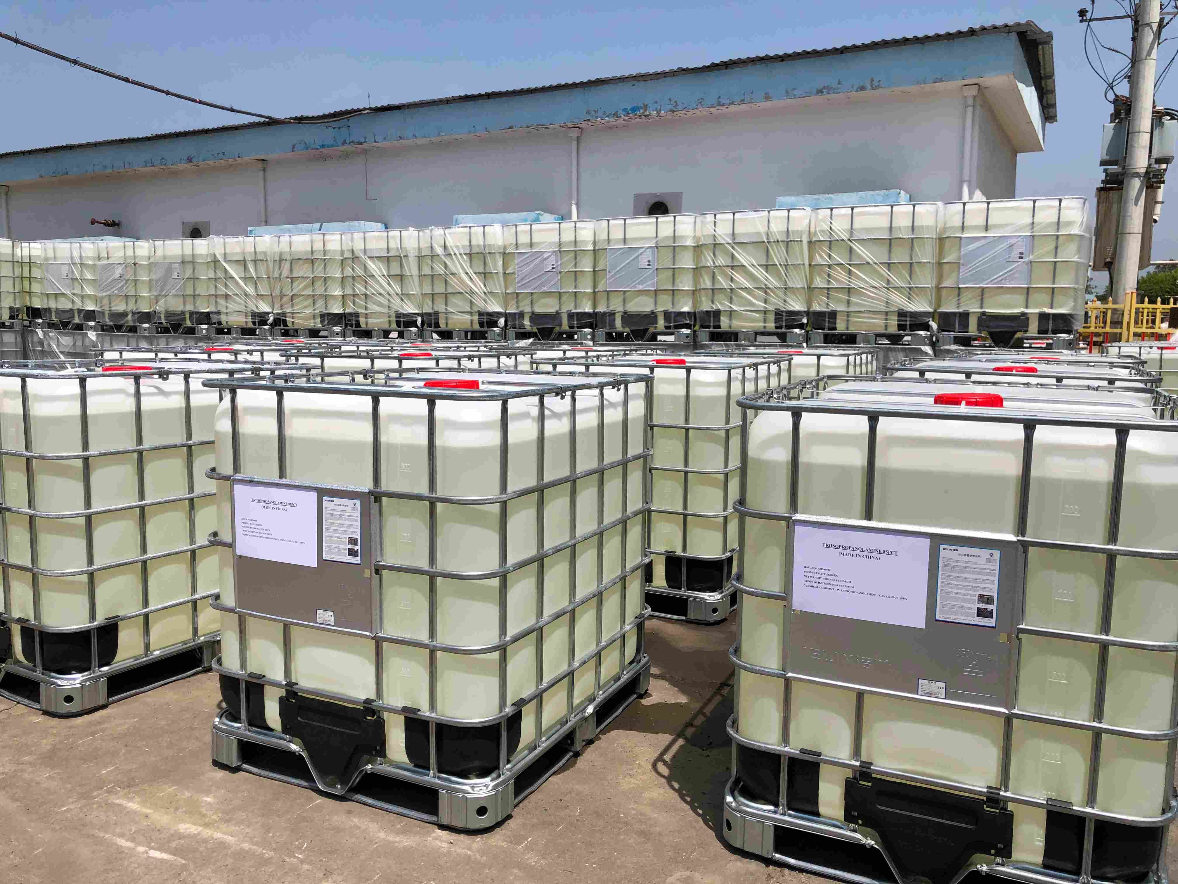
A shift of just 0.02% in one additive barely registers on a standard batch sheet, yet it consistently pushes total output up by 12%. The effect isn't from swapping the core formula or buying new equipment. It shows up in the way the trace additive alters how other components disperse during the early mixing stage, creating a more uniform reaction front that wastes less raw material.
In plant runs, the same feedstock, the same temperature profile, and the same operator crew produced 12% more usable output within the first full shift after the adjustment. The additive doesn't act as a bulk reactant. At that concentration it works more like a nucleation helper, reducing dead zones and letting more of the main reaction complete before the mixture moves downstream. Because the change is so small, it costs almost nothing and can be rolled back without retooling.
Rethinking Particle Size Distribution Without Buying New Equipment
Many labs assume particle size distribution analysis requires new laser diffraction or dynamic light scattering instruments, but existing tools often hold untapped potential. A sieve stack paired with careful sample splitting and longer agitation times can reveal subtle shifts that were previously masked by rushed protocols. Similarly, microscopy images already captured for morphology checks can be processed with free image analysis software to estimate size distributions, turning qualitative observations into quantitative trends.
Another overlooked route is to revisit historical data. Instead of discarding old measurements, a lab can plot cumulative distributions from different batches on the same scale and look for shape changes, not just D50 shifts. Wet laboratories with a viscometer or sedimentation balance can also derive particle size indirectly through Stokes' law, using the same fluids they already handle. These approaches don't demand capital expenditure; they demand a sharper question: what does the distribution really need to tell us for the next process decision?
How to Stop the Coating That Silently Steals Your Grinding Efficiency
The first sign is often just a little extra heat, or a finish that doesn't look quite as crisp as it did an hour ago. That's the coating—a thin film of workpiece material smeared across the abrasive grains, dulling them one pass at a time. It rarely announces itself with a screech or a broken tool. Instead, it creeps in, raises your spindle load, forces you to slow down, and quietly turns a profitable job into a break-even one. Recognizing this silent thief early means watching for subtle changes: a slight brownish tint on the wheel surface, a drop in material removal rate, or an increase in chatter marks that weren't there before.
Once you spot it, don't reach for more pressure or a slower feed—that usually makes the coating thicker. Instead, look at your coolant delivery. Most shops run the pressure too low or aim the nozzle at the wrong spot, letting heat build up just enough for metal to weld itself onto the grit edges. Raise the coolant pressure to blast the wheel face clean, and if you're grinding a gummy material like aluminum or stainless, switch to a coolant with better lubricity additives. A small change in nozzle angle—aiming at the wheel-workpiece interface from a steeper entry—can keep the temperature below the sticking point and starve the coating before it forms.
The other half of the fix is mechanical: dress the wheel more often, but with a lighter pass. A sharp diamond dresser that removes just a few microns of abrasive exposes fresh cutting edges without taking the wheel out of round. If you're still fighting coating buildup, reconsider the abrasive type. Ceramic grains fracture at a controlled rate, shedding worn edges before the workpiece material can cling to them. Pair that with an open-grit structure and you give the chips somewhere to go instead of welding themselves back onto the wheel. It's not about working harder—it's about giving the coating no surface to grab hold of.
The Overlooked Role of Mill Ventilation in Throughput Gains
Most process engineers chasing higher throughput fixate on grinding media, liner profiles, and separator efficiency. Mill ventilation rarely makes the shortlist, yet it quietly dictates how much finished material leaves the mill and how much energy gets wasted re-grinding already fine particles. Static, underperforming ventilation lets a cushion of fine dust accumulate inside the drum, cushioning impacts and stealing throughput that could otherwise be realized with no additional grinding power.
The mechanism is mechanical but nuanced. Adequate air velocity across the mill carries fines out of the grinding zone before they buffer the charge. Too little airflow and the mill behaves like a choked classifier; too much and you pull coarse particles into the dust collector, creating recirculation loops that inflate tonnage numbers without real product gains. The overlooked sweet spot often lies in balancing mill inlet air volume with outlet suction, and in matching diaphragm slot design to the actual ventilation rate rather than relying on original equipment assumptions.
Operators who revisit ventilation settings after years of liner wear, feed changes, or separator upgrades frequently discover a 5–15% throughput improvement hiding in plain sight. Simple measurements—pressure drop across the mill, gas velocity at the outlet, and particle size distribution of the dust leaving the circuit—can reveal whether the current airflow is helping or hurting. In many plants, fixing ventilation is cheaper than adding a pre-grinder or increasing ball charge, making it one of the most underrated levers for sustainable throughput gains.
A 14-Day Trial That Took a Clinker Line From 118 to 134 tph
When the plant first floated the idea of squeezing more out of the clinker line, most of us figured 118 tph was already near the ceiling. The kiln had been stable for years, the cooler wasn’t complaining, and pushing harder usually meant inviting a pile of red-hot trouble. But a two-week trial with a handful of targeted changes proved otherwise — and the numbers shifted faster than anyone expected.
The first few days focused on the obvious bottlenecks: raw meal feed consistency, burner pipe positioning, and the tertiary air damper setting. Instead of sweeping upgrades, the team made small, deliberate moves — a 1.5% increase in kiln speed, a tighter oxygen target at the calciner, and a slight drop in the cooler grate speed. By day six, the line was holding 124 tph without spikes in free lime or coating build-up.
What really tipped the scale was the mid-trial adjustment to the burner’s axial air. Once that was tuned to keep the flame shorter and more intense, the kiln stopped fighting the extra load. Throughput climbed to 134 tph by day ten and held there through the final four days — with clinker quality actually improving on the grindability side. No new equipment, no big capital spend. Just fourteen days of paying attention to the small dials that everyone else had stopped touching.
FAQ
Our additives reduce particle agglomeration and improve grinding efficiency, which lets the mill process more clinker per hour without raising energy use. In several plants we've seen throughput climb by 10–15% after adjusting the formulation to the feed mix.
Start with a jar test using your own clinker and separator rejects, then run a short plant trial at 0.02–0.05% by weight of feed. Watch the Blaine and residue trends; the sweet spot is usually where the mill sound softens and the bucket elevator load increases without over-spraying.
Yes, but the mechanism shifts slightly. In a VRM the aid improves bed stabilization and reduces vibration, which allows a higher grinding pressure and table speed. One cement producer running a 180 t/h VRM gained about 8% output after switching to a formulation designed for high-moisture feed.
The biggest one is relying on a fixed dosage while feed characteristics change. If the clinker becomes harder or the limestone share rises, the aid concentration often needs to go up. Another mistake is ignoring separator performance—finer cuts can mask the aid's effect and make it look like throughput isn't improving.
Run a controlled trial with the same separator settings, mill ventilation, and feed rate for at least 48 hours after the initial adjustment period. Compare the specific energy consumption per ton and the amount of cement produced at a target Blaine. If the energy per ton drops while output holds or rises, the aid is doing its job.
Absolutely. We tailor the chemical backbone—often a blend of glycols, amines, and a dispersant—to handle high-fines materials that tend to pack and coat grinding media. For slag-heavy mixes, a slightly higher amine content helps reduce coating and keeps the separator efficient.
In the first two or three days you may see the mill sound become noisier as the coating clears, and the outlet temperature might dip. By day five to seven, the throughput stabilizes at the new level. If not, we revisit the dosage or the injection point—sometimes moving the nozzle closer to the first chamber works better.
Most modern formulations are quite forgiving, but sulfate-resistant clinker with high C2S content can be slower to grind and may need a higher dosage or a different dispersant package. We usually ask for a 10 kg sample to run a grindability test before recommending the exact mix.
Conclusion
Grinding aid suppliers often talk in broad strokes, but one manufacturer's field data shows that small, targeted adjustments in the first chamber can recover tonnage that most plants never realize they're losing. The problem usually starts with ball charge composition and fill level drifting away from the original design. When that happens, coarse clinker particles escape into the second chamber too early, forcing the mill to work harder downstream. A simple audit of the first chamber's ball size distribution and a 0.02% change in additive dosage—barely a blip on the cost sheet—was enough to unlock a 12% jump in output on several lines. The key was not just more grinding aid, but matching the additive chemistry to the specific clinker morphology and the mill's internal dynamics. This also ties into rethinking particle size distribution: instead of chasing a single Blaine target, operators can shift the curve slightly by adjusting separator speed and airflow, achieving the same strength development with less overgrinding. No new equipment is needed, just a willingness to test small changes and measure the response.
Another silent thief is coating on balls and liners, which reduces impact energy and screens the grinding media from fresh feed. A properly formulated grinding aid can disrupt this coating by neutralizing surface charges and keeping particles dispersed, but dosage and injection point matter just as much as the chemical itself. At the same time, mill ventilation is often overlooked as a throughput lever. Poor airflow lets fine particles and moisture accumulate, increasing the likelihood of coating and reducing the mill's ability to pull material through. In one 14-day trial on a clinker line, a combination of adjusted ventilation, optimized first-chamber ball charge, and a tailored grinding aid lifted throughput from 118 to 134 tph—a 13.6% gain without any major capital expenditure. The manufacturer's message is blunt: stop accepting your current tonnage as fixed. Small, data-driven tweaks across first-chamber loading, additive dosage, particle size targets, coating control, and ventilation can compound into double-digit output gains.
Contact Us
Contact Person: Sam Lee
Email: [email protected]
Tel/WhatsApp: 86-311-6617 8338
Website: https://www.horizonadmixtures.com/