

Big Industrial Fans Factory: Inside the Manufacturing of Heavy-Duty Airflow Systems
2026-09-21
Stepping onto the floor of a big industrial fans factory, you don’t just see machinery—you feel the pulse of heavy-duty airflow systems taking shape. From raw steel to roaring blades, every stage of production reveals why reliability matters at scale. In this post, we go behind the scenes to explore how VINDUSFAN turns engineering precision into the powerful ventilation solutions that keep industrial environments moving.
Where Raw Steel Meets Rotor Dynamics
The hum of a high-speed rotor begins long before the first spin on the test stand. It starts in the grain structure of a steel billet, where residual stresses, inclusions, and micro-voids silently dictate how that metal will behave at 30,000 rpm. Many engineers treat rotor steel as a homogeneous blank, but the truth is messier and more interesting: every heat of steel carries a unique signature, and matching that signature to a specific rotor geometry is where the real work happens.
Rotor dynamics calculations typically assume perfect isotropy — the same stiffness and damping in every direction. Yet raw steel plate or forged bar stock never cooperates fully. Fiber orientation from rolling, uneven cooling after quenching, and even the location where the material was cut from the parent ingot introduce asymmetric behavior. A rotor that simulates beautifully on paper can develop split critical speeds or unexpected whirl modes once the metal's hidden anisotropy wakes up under centrifugal load.
That's why practical rotor design now folds material pedigree into the dynamic model. Rather than treating Young's modulus as a textbook constant, engineers pull measured values from the actual billet, including through-thickness properties and damping loss factors at operating temperatures. The payoff isn't just fewer failed spin tests — it's the ability to push a rotor closer to its true stability limit without gambling on an idealization. Raw steel isn't the enemy of good rotor dynamics; it's the untapped collaborator.
Laser Cutting the Backbone of Airflow
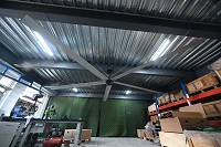
Airflow systems live or die by the tolerances in their structural seams. Laser cutting removes the wobble and ragged edges that traditional punching or shearing leave behind, so each manifold, plenum, or louver slots into place without gaps. That precision matters most where pressure differentials are tight and even a half-millimeter leak can turn a smooth stream into turbulence.
On the shop floor, the process also shortens the path from flat sheet to finished ductwork. Nesting software arranges complex elbow profiles and flange cutouts across the metal with minimal scrap, while the laser's narrow kerf preserves detail in thin-gauge aluminum and stainless steel. The result is a backbone that holds its shape under load and still fits the surrounding frame without forcing installers to fight the assembly.
The Art of Welding Heavy-Duty Hubs
Welding a heavy-duty hub is less about brute force and more about reading the steel like a living map. Every pass of the torch leaves a signature, and the real craftsmen know when to linger in the throat of a fillet or pull back on a root pass before the puddle drowns the edges. Heat input becomes a language: too much and the hub loses its temper, too little and you're just painting cracks over a hidden void. The best welders don't work from a checklist; they feel the rhythm of the arc and adjust on the fly, letting the metal tell them where it needs to settle.
There's a quiet discipline in prepping a hub that most outsiders never see. It starts with grinding away the old weld's shadow, chasing pitting down to clean parent material, and then laying a series of tack welds that act like punctuation marks holding the assembly in line. On thick sections, the interpass temperature matters more than the amperage dial, because a hub that cools too fast will hide its stress in the grain structure until the first hard load snaps it clean. Veterans will tell you that the true test isn't the outside bead—it's whether you can run a grinder down the inside radius and find no undercut, no trapped slag, no apology for a lack of patience.
And then there's the final inspection, which is as much about touch as it is about sight. Running a gloved finger over a finished weld on a heavy hub tells you whether the cap was laid with intent or just smeared on to look full. The art lives in the small choices: switching to a smaller filler rod for the cover pass to keep the toes wet, rolling the piece just enough to let gravity shape the crown, or knowing exactly when to stop and let the metal cool before the next run. A hub that's welded this way doesn't just survive torque and vibration—it carries a quiet history of the hands that built it, and that's what separates a part from a piece of craft.
Balancing Blades for Vibration-Free Spin
Every rotor starts with tiny asymmetries. A few grams here, a slightly denser section there—once it spins up, those small differences turn into rhythmic shove that travels through bearings and housings. Balancing isn’t just about adding or shaving weight; it’s about finding the actual heavy spot, not the spot where vibration seems loudest. That distinction catches a lot of people off guard.
On fast spindles, even a fraction of an ounce can excite a resonance that becomes impossible to ignore. The trick is to measure phase as well as amplitude. Knowing how far the heavy point leads the vibration sensor lets you place correction weight where it actually cancels the wobble instead of chasing it. It becomes less of a guess and more of a mechanical conversation.
Once the blades are matched and the hub is trued, the spin should feel almost silent. No low-frequency rumble climbing up the frame, no high-speed whine that comes and goes. That quiet is the real test—after all, vibration-free doesn’t come from luck, but from respecting the tiny errors that try to amplify themselves at speed.
Motor Assembly: The Heartbeat of the Fan
The motor assembly isn’t just another part tucked behind the blades—it’s what gives the fan its character. A well-built motor spins with a low, steady hum instead of a rattle, and that difference comes down to how the rotor and stator are aligned, the quality of the copper windings, and the grade of the bearings. When you switch a fan from low to medium, you’re not just changing a resistor setting; you’re asking the motor to shift its torque curve smoothly without losing balance.
What often gets overlooked is heat. A motor that runs hot will gradually loosen its windings and wear out its lubricant, turning that once-quiet heartbeat into a grinding pulse. Good designs include ventilation slots or a thermally protected housing, so the fan can run for hours on a summer night without the motor cooking itself. That’s why the motor’s placement—whether it’s fully enclosed or exposed to airflow—matters more than its wattage on paper.
In practical terms, a fan with a sluggish start, a burnt smell, or a wobble that worsens over time is telling you the motor assembly is struggling. The fix often isn’t the blade or the guard; it’s lubricating the front and rear bearings, checking the capacitor that feeds the start winding, or replacing the entire motor unit. Once you understand that the motor is the real heart, maintenance becomes less about guesswork and more about listening to that steady beat.
Endurance Testing Beyond Factory Walls
Durability assessments rarely stop at the production line. Real-world longevity depends on how a product behaves after months of exposure to uneven roads, temperature swings, and user habits that no lab can fully replicate. Field endurance testing takes the evaluation into everyday environments, capturing failures that surface only when components are pushed beyond their factory-defined limits.
One practical approach involves equipping a small fleet of devices with logging sensors, then handing them to a mix of early adopters and heavy users. These participants go about their normal routines while the devices record stress events, battery drain, and mechanical wear. The resulting data often contradicts bench tests—showing, for example, that a hinge rated for fifty thousand cycles begins to loosen after just a few weeks in a sandy coastal climate.
What makes this phase valuable is its unpredictability. Unlike controlled chambers that simulate a fixed set of conditions, outside testing introduces overlapping variables: humidity combined with vibration, or dust followed by rapid cooling. Engineers use these findings to adjust materials, tighten tolerances, or redesign seals. Without this broader view, a product might pass every factory check yet still disappoint customers within its first year of use.
FAQ
The main difference is the engineering tolerance and material thickness. Heavy-duty units are built for continuous operation, often 24/7, in harsh environments. That means thicker steel housings, reinforced bearing assemblies, and impellers that are dynamically balanced to much tighter vibration limits than a typical warehouse fan. The factory also performs more weld inspections and stress-relief steps to prevent fatigue cracking over years of service.
Balancing is done in two stages. First, each blade is weighed and matched so the total weight difference across the set is minimal. Then the assembled impeller goes onto a dynamic balancing machine that spins it at operating speed. The machine identifies heavy spots, and technicians either add counterweights or remove a small amount of material from the hub. It often takes several iterative runs to get the residual unbalance down to a few grams, even on a multi-ton rotor.
For thick steel sections, the factory typically uses a mix of MIG and TIG welding. MIG handles the long, heavy structural seams quickly, while TIG is used for root passes and areas where air tightness is critical. Welders also use back-step sequencing and temporary stiffeners to control distortion. After welding, the housing gets a leak test using pressurized air and soap solution to spot any pinholes before painting.
CNC gets the geometry close, but hand finishing addresses surface defects and edge conditions that influence airflow and fatigue life. A skilled technician will deburr sharp edges, blend weld profiles, and sometimes polish the leading edge of an airfoil blade. These small adjustments reduce local stress concentrations and can slightly improve aerodynamic efficiency. It is also a final visual check for cracks or material flaws that automated processes might miss.
The test rig measures airflow volume, static pressure, power draw, vibration velocity, and bearing temperature at several operating points. The fan is run through its full RPM range, including an overspeed test, while sensors log data. If the vibration signature shows an unusual spike or the airflow falls short of the rated curve, the unit is pulled for diagnosis. Sometimes the fix is as simple as re-balancing; other times the impeller pitch needs adjustment.
Explosion-proof fans use non-sparking materials for the impeller and inlet cone, such as aluminum or bronze, and the motor is fully enclosed with a flameproof housing. All electrical connections are sealed, and the entire assembly is grounded to prevent static buildup. The factory also avoids any rubbing contact between rotating and stationary parts, often using a wider tip clearance, because friction sparks are a serious ignition risk in dusty or gas-laden air.
Most fans over a certain diameter are shipped in modules. The housing may be split into two or three sections, the impeller is shipped separately with a balancing report, and the drive system is packed in crates. The factory provides a detailed assembly manual and sometimes sends a supervisor for complex installations. Fully assembled shipping is usually limited to smaller units under about two meters in diameter, simply because of road width and height restrictions.
Look for split housings that allow blade access without removing the entire fan, self-aligning bearing pedestals, and grease lines extended to a single lubrication point. Some modern designs include vibration sensors mounted directly on the bearing housings with cable connections to a monitoring panel. Also check if the fan has a hinged inspection door and whether shaft seals can be replaced without disassembling the bearing assembly. These features can cut routine maintenance time by more than half.
Conclusion
Stepping into the facility, the first thing you notice is how raw steel behaves less like inventory and more like a living material with its own tension and memory. Before any rotor takes shape, engineers map resonance frequencies and grain direction, because a heavy-duty fan is only as stable as the steel it starts from. The backbone of every airflow system emerges from laser cutting bays where precision meets speed; beams slice through plate with a hiss, leaving edges clean enough that downstream welding doesn't have to fight geometry. Then comes the hub welding, a process that feels closer to sculpture than assembly. Welders work in slow, deliberate passes, building up the central mass that will later carry tons of rotating force. It is not enough to simply join metal; the heat input must be managed so the hub retains its concentricity and fatigue strength.
Once the major components are fused, each blade assembly goes through dynamic balancing. Technicians add or remove tiny amounts of weight while the rotor spins at operational speed, chasing the kind of silence that only comes from near-perfect mass distribution. The motor is then mated to the hub; this is not a bolt-on afterthought but a carefully aligned marriage of shaft, bearing, and stator, because even a fraction of a millimeter off center can turn into destructive vibration at full load. Finally, the finished fan faces endurance testing that goes beyond factory walls in its simulation. It runs through thermal cycles, dust exposure, and load spikes that mimic years of service in a matter of days. Only after those trials does the fan earn its place on the factory floor, ready to move air through mines, mills, and power plants where failure is not an option.
Contact Us
Contact Person: Michael Danielsson
Email: [email protected]
Tel/WhatsApp: +1 951 565 7769
Website: https://www.vindusfans.com